Topology
Prerequisites
-
Role
-
Show facilities
UserorExpertorAdministrator -
Edit facility
ExpertorAdministrator -
Import/add/delete facility, create/disconnect/delete connections, connect facility to devices/measuring points/error definitions, import error definitions for facility
Administrator
-
Procedure
-
In the menu, click Master data management > Equipment > Topology.
The Topology tab appears with the following sections up to and including the production line element class:
-
Tool box (left)
The available mixed elements of the topology (IAS and MES) are located here, each divided into five classes:
| Class | Description |
|---|---|
Company |
All facilities and hierarchy objects at the enterprise level |
Location |
All facilities and hierarchy objects at the production site level |
Production area |
All facilities and hierarchy objects at the production area level |
Production Line |
All facilities and hierarchy objects at the production line level |
Work unit |
All facilities and hierarchy objects at the work unit level |
|
Elements of the Work unit class are initially hidden when the topology is opened. To show the Work unit , use the child element filter. |
To hide or show the toolbox, click  or
or  .
.
-
Working area (right-hand pane)
The actual topology is shown here. It can be changed with elements from the toolbox.
Changes in the topology have an immediate effect.
For more information about the Topology tab, see the following sections.
Import facilities
Plants, products, areas, lines, station indices, own function units, tool positions and work positions can be imported based on a CSV or XML file. The topology is structured according to the imported information. All topology configurations support the CSV format, while XML is only supported by the legacy topology configuration.
First, make sure the topology is set to the right configuration:
-
In the toolbar, click the configuration icon to select the appropriate topology.
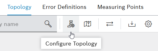
The Topology Configuration dialog appears.
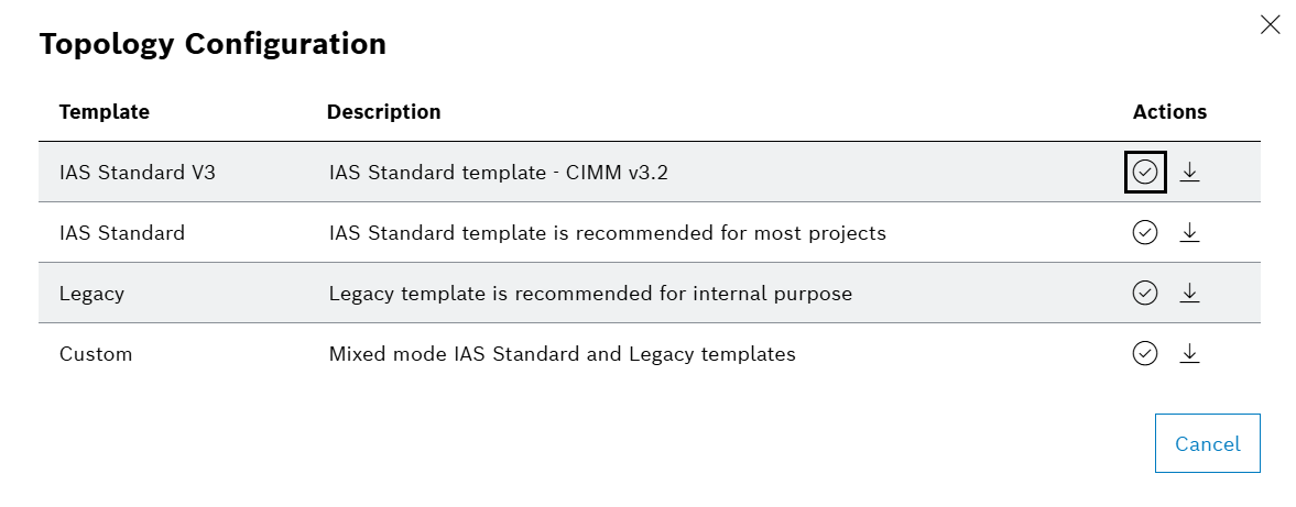
-
Select the desired configuration and click the Confirm icon.
To import, follow the steps below:
-
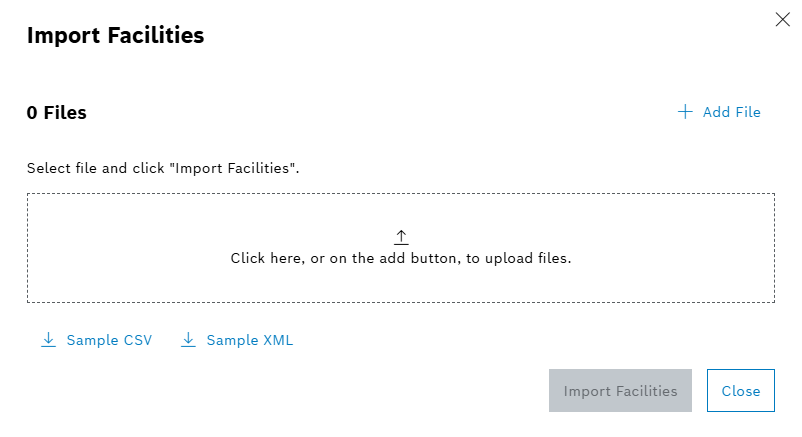
In the toolbar, click
 .
.The Import Facilities dialog appears.
-
Click Sample to download a CSV or XML template for importing facility information.
-
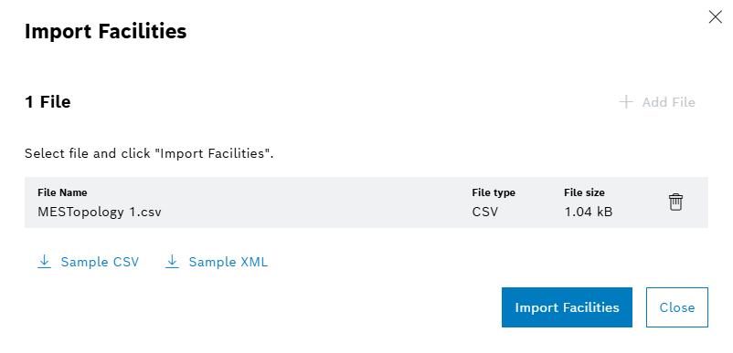
Select the file using either the Add File button,by Click on the marked area or drag and drop the files to the marked area.
Only one file may be selected.
-
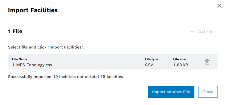
Click on the Import Facilities button to start the process, or click Close to cancel.
-
After the import is completed, you can import another file by clicking on Import another File button.
-
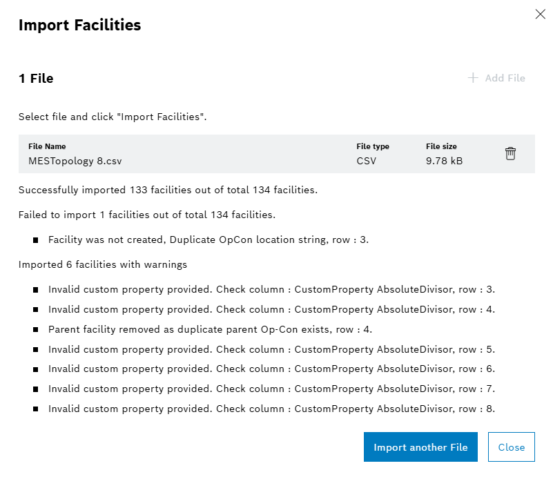
During the import, information on the number of data points read or written, errors and warnings that occurred is displayed.
-
After the import is completed, click Close.
-
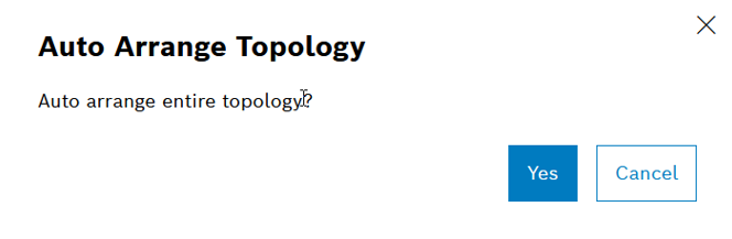
You can choose to auto arrange the newly imported elements by clicking on Yes.
The facility has been imported. All the imported facilities with their relations appear in the working area.
Add facility
-
Drag and drop an IAS or MES device from the corresponding tab of the tool box in the left-hand area ( Topology ) into the work area.
The facility appears in the topology.
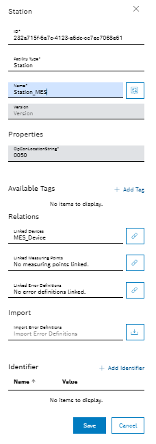
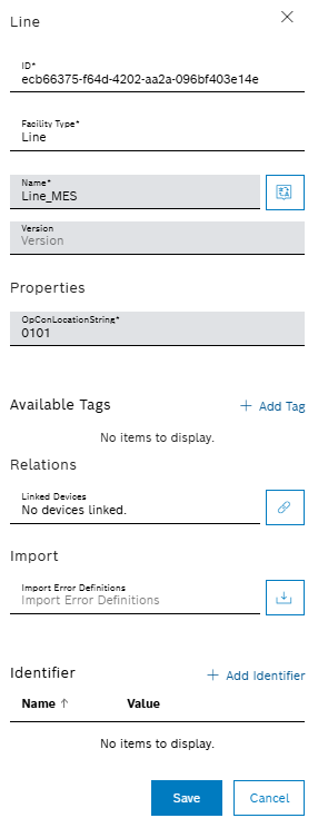
The dialog for specifying the properties of the facility appears (in example: IAS facility type work unit).
-
Enter details:
-
In the Name text box, enter the name of the facility.
-
In the Version text box, enter the version of the facility.
-
Click
 and enter the translations of the names of the facility in the other supported languages.
 -
Assign existing or newly created tags to the facility in the Available tags area using Add tag. Further information: Create, Add, Remove and Delete tags.
-
In the Linked devices selection box, you can link the facility to devices. Further information: Link Facility to Devices.
-
In the Linked measuring points selection box, you can link the facility to unique measuring points. Further information: Connect facility to measuring points.
-
In the Linked error definitions selection box, you can link the facility to unique error definitions. Further information: Connect facility to error definitions.
-
Assign existing or newly created designators to the facility in the Identifier field using Add Identifier. Further information: Create, Add, Remove and Delete Identifiers.
This dialog can be called up again at any time to change properties.
-
-
Click Save.
The facility is added to the topology, but not yet linked to others.
Create, add, remove and delete tags
-
Double-click the facility in the work area.
The dialog for specifying the properties of the facility appears (in example: IAS facility type work unit).
-
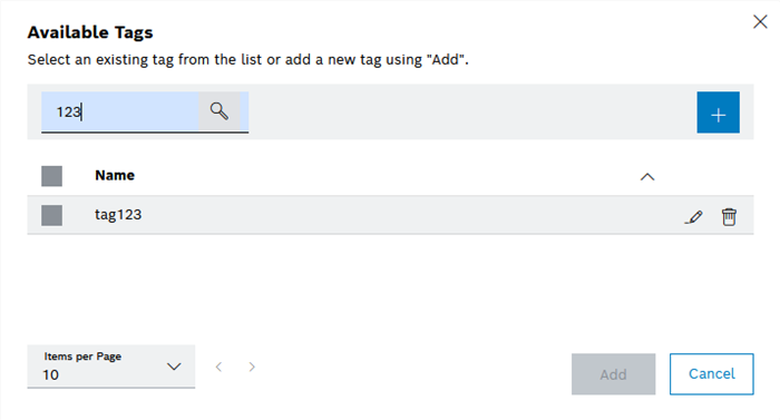
To add a tag in the Available tags area, click Add Tag.
The Available tags dialog appears.
-
Enter details:
-
In the Search field, enter one or more characters to search for an existing tag.
-
In the Available tags list, click to select one or more tags.
-
-
Click Add to assign the tag(s) to the facility.
The tag(s) is/are added to the device and will be displayed in Available tags.
-
Click
 to create a new tag.
The Create tag dialog appears.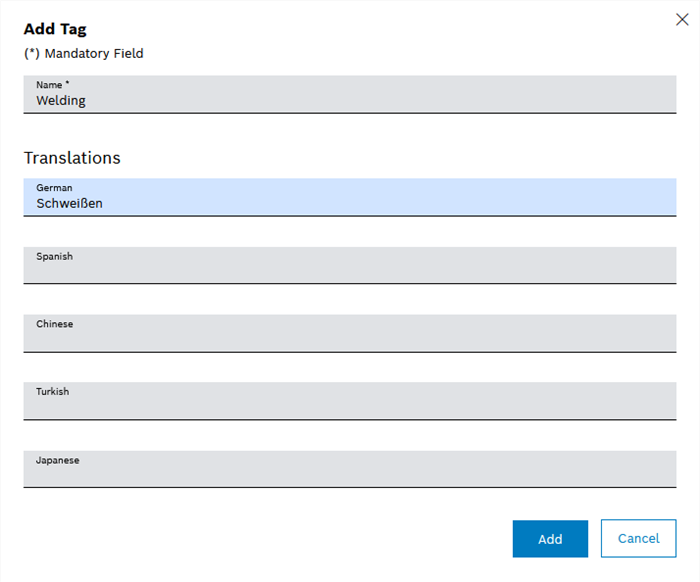
-
Enter details
-
In the Name text field, enter the English name of the tag.
-
Enter the names of the tag in the other supported languages in the Translations area.
-
-
Click Add to save the tag.
The tag will be created and will appear in the list of available tags.
To remove a tag, in Available tags click  of the relevant tag.
Create, add, remove and delete Identifiers
-
Double-click the facility in the work area.
The dialog for specifying the properties of the facility appears (in example: IAS facility type work unit).
-
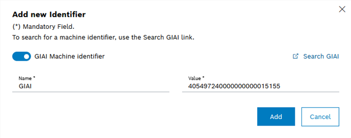
To add an identifier, in the Identifier area, click Add Identifier.
The Identifier data dialog appears.
-
Enter details:
-
Enter the English name of the identifier in the Name text field.
-
In the Value text field, enter the value of the designator. The entered Value does not have to be a specific data type.
-
-
Click Add to save the identifier.
The identifier is created and appears in the list of available identifiers.
To edit a designator, in Designators , click  in the row of the designator you wish to edit, make the changes and save.
To remove an identifier, under Identifier , click  in the row of the identifier you wish to delete, then click Delete identifier.
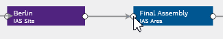
Create connection
A connection is established between two devices at different hierarchy levels.
-
Place the mouse pointer over the connection point of one device.
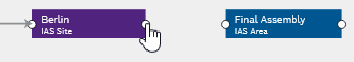
The mouse pointer changes to the Hand icon .
-
Click and hold the connection point.
Possible target devices retain their strong color, all other devices are shown in a faded color.
-
Move the mouse pointer to a possible target device while holding down the mouse button.
A dotted connection line appears.

-
Release the mouse button.
A solid connection line is displayed between the two devices.
The two devices are connected.
Delete connection
-
Place the mouse pointer over the connection line between two devices.
 appears on the connection line.
 -
Click
.The Delete connection dialog is displayed.
-
Click Delete connection.
The connection line is no longer displayed. The two devices are no longer connected.
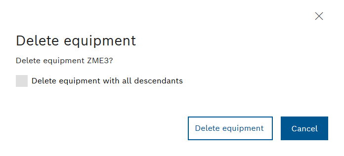
Delete facility
-
Place the mouse pointer over the facility you want to delete.
 appears.
 -
Click
.The Delete facility dialog appears.
If the device has at least one connection to a child element, the Chose Delete Option dialog appears.
-
Read the dialog carefully and click the checkbox.
-
Click on Delete.
The facility is deleted (including any child elements if selected) and no longer appears in the topology.
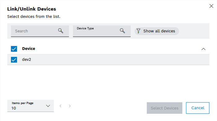
Link facility to devices
All elements in the topology can be connected to devices.
-
Double-click the element you want to connect.
The dialog for specifying the properties of the facility appears (in example: station).
-
Under Relationships , next to the Connected devices field, click
 .
.The Connected devices dialog appears.
-
Enter details:
-
In the Select device type field, filter by a device type.
-
In the Search field, search for one or more devices.
-
Activate the checkbox of at least one device to be connected.
-
-
Click Select devices.
The facility is linked to at least one device.
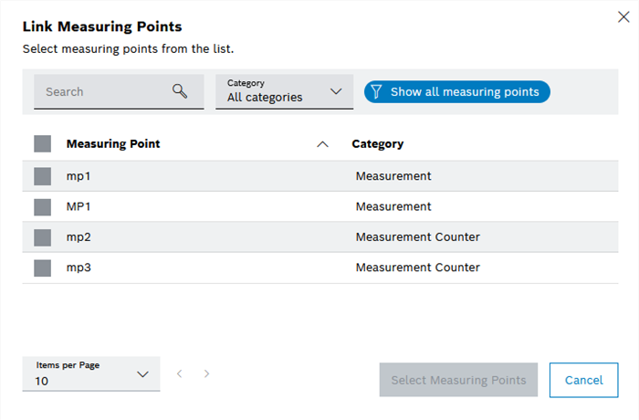
Connect facility to measuring points
Stations, functional units, station indices, tool positions and working positions can be connected to measuring points.
-
Double-click the element you want to connect.
The dialog for specifying the properties of the facility appears (in example: MES station).
-
The Connect measuring points dialog appears.
-
Enter details:
-
In the Category drop-down list, filter by a category.
-
In the Search field, search for measuring points.
-
Activate the checkbox of at least one measuring point to be connected.
It is not possible to connect an item of facility to multiple measuring points with the same name and category.
-
-
Click Select measuring points.
The facility is linked to at least one measuring point.
Connect facility to error definitions
Stations, functional units, station indices, tool positions and working positions can be connected to error definitions.
-
Double-click the element you want to connect.
The dialog for specifying the properties of the facility appears (in example: MES station).
-
Under Relationships next to the Connected error definitions field, click
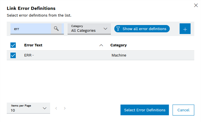
.The Connect error definitions dialog appears.
-
Enter details:
-
In the Category drop-down list, filter by a category.
-
In the Search field, search for one or more error definitions.
-
Activate the checkbox of at least one error definition.
It is not possible to connect an item of facility with multiple error definitions of the same name and category.
-
-
Click
to create a new error definition.
The Create error definition dialog appears.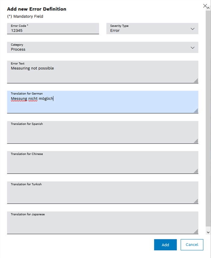
-
Enter details:
-
In the Error code text box, enter the alphanumeric error code.
-
In the Severity selection box, you can select the severity of the error.
-
In the Category selection box, you can select the category of the error, for example:
Machine : Error on the machine
Measurement : Error during the measurement
Process : Process error
ProcessNOKBit : Process error in bit form
-
In the Error text text field, you can enter the German text that is to be displayed when the error occurs.
-
In the Translation for English text field you can specify the English text that is to be displayed when the error occurs.
-
In the Translation for Spanish text field, you can specify the Spanish text that is to be displayed when the error occurs.
-
In the Translation for Chinese text field, you can specify the Chinese text that is to be displayed when the error occurs.
-
In the Translation for Turkish text field, you can specify the Turkish text that is to be displayed when the error occurs.
-
In the Translation for Japanese text field, you can specify the Japanese text that is to be displayed when the error occurs.
Further information on translating the error texts into other supported languages: Translate error definition
-
-
Click Add.
The new error definition appears in the list and is selected. -
Click Select error definitions.
The facility is linked to at least one error definition.
Import error definitions for facility
Error definitions for lines, stations, station indices, own function units, tool positions and work positions can be imported.
-
Double-click the element you want to connect.
The dialog for specifying the properties of the facility appears (in example: station).
-
Under Import , next to the Import Error Definitions field, click
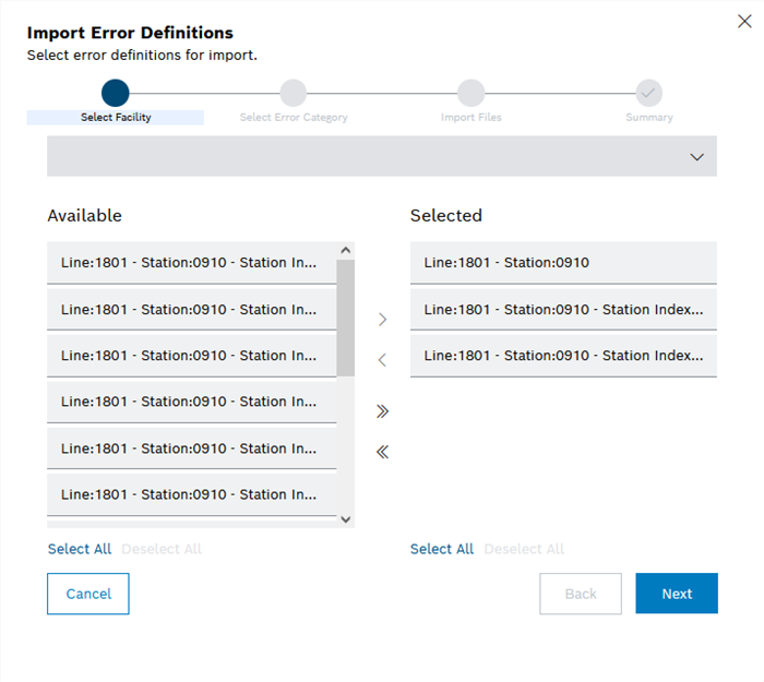
.The Select facility step of the Import error definitions dialog appears.
-
Use the Select facility type drop-down list to filter by facility type.
-
Move facility to the Selected table to select it or remove facility from the Selected table to deselect it.
-
To select facility, specify the following:
To select facility, activate the checkbox of the required facility in the Available list and click
.Or:
In the Available list, double-click the entry of the desired facility.
Or:
In the Available list, click the required facility and drag and drop it into the Selected list.
-
To select all facilities, specify the following:
To select all facilities, activate all checkboxes, click Select all or click
 .
.All facilities are added to the Selected list.
-
To deselect currently selected facility, specify the following:
To deselect facility, activate the checkbox of the relevant facility in the Selected list and click
.or
In the Selected list, double-click the entry of the desired facility.
or
Click the relevant facility in the Selected list, hold the mouse button down, drag the column to the Available list and then release the mouse button (drag and drop).
-
To deselect all currently selected facility, specify the following:
To hide all columns, activate all checkboxes, click on Select All or click on
 .
.All facilities are added to the Available list.
-
-
Click Next.
The Select error category step of the Import error definitions dialog box appears.
-
Select an error category from the drop-down list.
-
Click Next.
The Import files step of the Import error definitions dialog box appears.
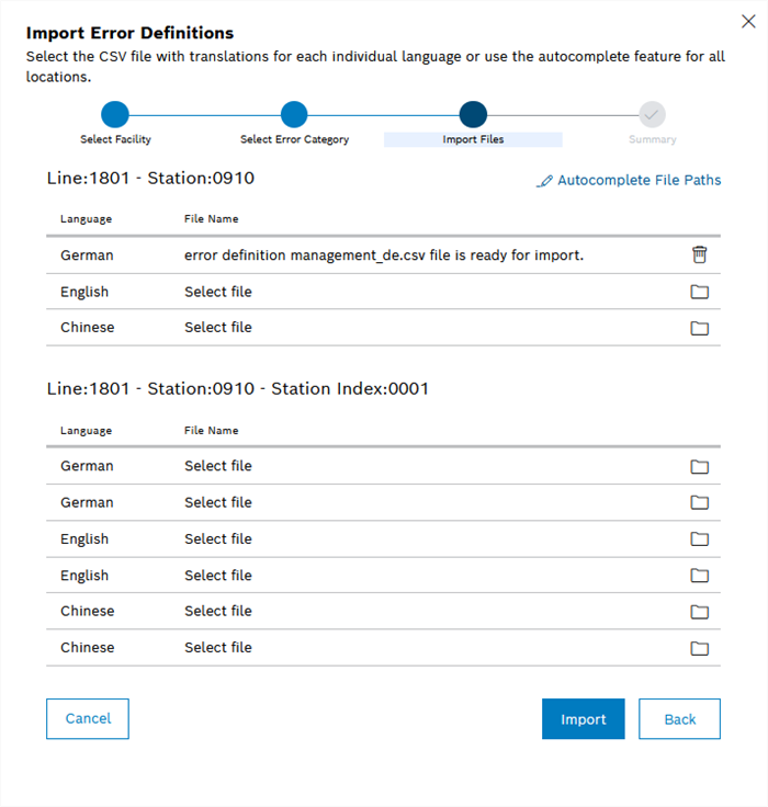
-
Select files to import using one of the following methods.
-
For the required language, click
 and select the CSV file to import in the file system.
The name of the selected file appears in the File name column.
Repeat for other required languages if necessary.
-
Click Automatic file selection and select a folder in the file system. The CSV files to be imported that are pre-populated in the list are automatically searched for in this folder.
To exclude a file from the import again, click
in the relevant line.
-
-
Click Import.
The Import complete dialog opens with a notification regarding the result of the file import.
-
To import more files, click Import more files.
-
To show a summary of the import, click Show summary.
The Summary step of the Import Error Definitions dialog appears. * To copy the summary, click Copy to Clipboard.
+ image::mdm_topology_equipment_import_error_definition_summary_2023-02-02.png[mdm_topology_equipment_import_error_definition_summary_25]
-
To import error definitions again, click Back.
-
To finish importing error definitions, click Close.
-
The error definitions for the facility have been imported in the required languages.