Control of the processing sequence
Controlling the processing sequence is the main function of Line Control. It allows you to define the steps a product must go through, known as the route list. Each station in the line must request production release for every product. If approved, the station performs its process; if not, the product passes through without processing.
After a process is completed, the station must notify the Line Control service so the next step can be determined. There are two ways to evaluate the next processing step:
-
Station-side evaluation: The station explicitly specifies the next step. This approach is used when product-specific rules or data only available at the station are needed to select the next process.
-
Server-side evaluation: The client sends only the processing result. The server calculates the next step using its own rule set, which cannot be changed by the client.
In some production lines, products are grouped and processed together. For these cases, group-based processing can be used. This reduces the number of messages sent and improves production cycle time, as all group information can be sent in a single message instead of one per part.
To identify the processing step, the client sends a process number for the intended process. This focuses on process rather than on equipment (machines or stations). If process numbers are not available, the station can be identified using the OpCon location scheme provided in the Equipment Editor (→ Route List Editor), which the server then maps to a process number.
Process vs. location
Understanding the distinction between location and process is essential. In Line Control, a location refers to the physical machine that executes one or more processes. For example, a machine may be designed to assemble connectors onto products. To perform this task, the station integrates subsystems such as a press-in unit or a vision system for inspection, ensuring correct assembly.
These subsystems are general-purpose units and can be utilized in various machines and applications. The machine leverages these subsystems to implement specific processes, typically by running dedicated software that defines how each subsystem should operate. This often involves configuring parameters tailored to the task, such as setting detection patterns for a vision system to identify components.
In Line Control, a production process refers to the specific task or operation performed to manufacture a product, such as "Connector Press In" or "Connector Inspection." Each process defines the exact step required in the production sequence.
A location, by contrast, identifies the physical or logical position of a machine within the production line or shop floor, such as "Station 40 on Line 8030." The location does not determine which process is performed; it only indicates where the machine is situated. If a machine is moved to a different line, its location changes, but the processes it performs remain the same.
Example
The following picture shows a machine implementing the two features Press In and Vision inspection. The machine has been designed to assemble connectors to products. To realize this task, the machine has used the two features Press In and Vision to implement the processes "Connector Press In" (using Press In feature) and "Connector Inspection" using the vision feature.
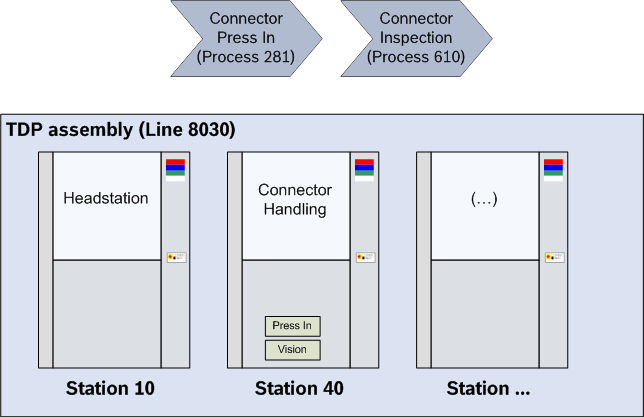
The machine itself will be used as part of an assembly line. Here in the example, the line is identified by the line number 8030 and the machine will be the station 40 of the line.
Route lists
A route list defines the sequence of production steps (processes) that a product must follow. Each process is represented as an entry in the route list, and the list itself specifies the order in which these steps are performed.
Different products may require different sets of production steps. Line Control supports multiple route lists to accommodate this. The client registering a work part at Line Control determines which route list will be used for that part.
After the Line Control dataset has been created, the link of the route list is stored inside the Line Control dataset and will be managed by the Line Control server.
A route list specifies all processes required to manufacture a product. Every process that may be executed must be included in the route list; otherwise, it will never receive a positive production release. Beyond listing valid processes, the route list defines their sequence and the conditions under which each process is executed.
Each process in the route list is represented by a production step. Every production step can specify up to five possible target steps, determining the next step based on the outcome of the current process. The default behavior of Line Control is as follows:
-
the first target will be next if the process has been regularly executed
-
the second target will be next if the processing was unsuccessful
-
the third target will be used if the work part must be scrapped
-
the fourth target will be a custom-specific target
-
the fifth target will be used if the work part must re-run the process
For each of the target a processing step can be defined. If no target has been defined for a specific target, the target cannot be used. If a process wants to move the work part to such a target, an error message will be returned and the work part remains on the process.
Example
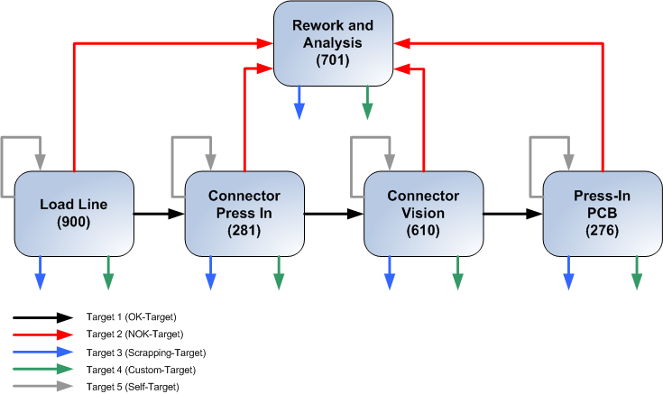
In this example the work part can be processed by the following processes:
-
Load Line
-
Connector Press In
-
Connector Inspection
-
Rework
As shown in picture, all processes are defined as processing steps inside the route list. Normally the processing steps will have the same names as the assigned processes but this is not required.
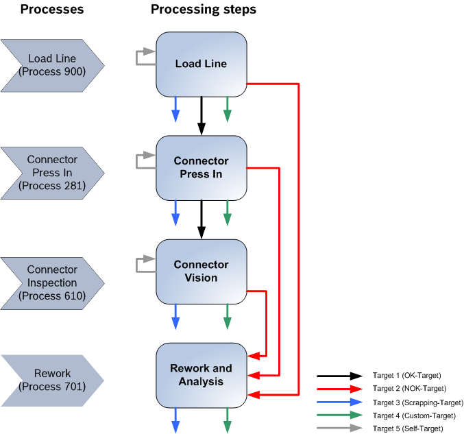
In the next step, the targets for the processing steps are defined. In this example, only the OK (successful processing) NOK (processing was not successful) and the self-target have been specified. So if the Process "Connector Press In" has been executed successfully, the process "Connector Vision" must be executed next. If the machine was not able to press in the connector, the "Rework" process must be next in order.
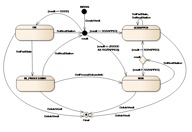
Work part state model
As shown in the Route lists section, each processing step could contain targets for various processing results. Beside this information, Line Control could manage the work parts state also. For this a state model has been defined, containing the typical work part states:
-
OK
The work part is in good shape and the next process can be executed
-
IN_PROCESSING
The work part is currently handled by some process.
-
NOK
The work part has a defect and no further processing except rework is allowed for the work part.
-
SCRAPPED
The work part has a serious defect and must be scrapped. No further processing / rework are allowed for the work part. Once a work part has entered the SCRAPPED state, it remains in this state.
The state information will be stored in the PartState property of the work part. If you have worked with previous versions of Line Control, you might notice that the OpCon PLC libraries have more than these states for a work part. You could still set the PartState property to one of these values, but Line Control will interpret these additional states always as NOK.
For all work parts which are not SCRAPPED, it is possible to set a new state by calling the SetPartState command. For example, you might want to set a work part into the IN_PROCESSING state if a process has started its work. Or if a work part is NOK, the rework process has the option to set the state to OK again.
Beside the SetPartState command the SetNextStation command will also affect the state of the work part. In case the station will send the new state, this state information will be used. Otherwise Line Control will calculate the new state of the work part using the processing result of the process.
The following picture will show you the most important transitions in the state model. To keep the diagram simple, some transitions have been left out (e.g. transitions for the various SetPartState calls).
Process control
Once at least one route list is defined, the Line Control server manages the processing sequence. The station responsible for the first process in the route list must register the work part with Line Control. Each subsequent station sends a production request and a process end message for every process it performs. The final station in the sequence must deregister the work part from Line Control instead of sending a process end message.
Example
The following picture will show you the typical messages for a work part running through a production:
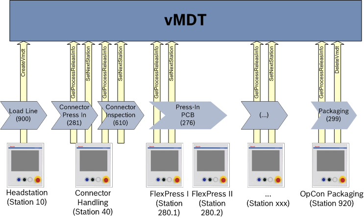
In this example, the Station 10 runs the initial process for the work part. Because the work part is first unknown inside Line Control, the Headstation must register the work part calling CreateVmdt. With this command, the work part will be registered at Line Control and the route list which should be used for the work part will be assigned to it. The work part moves to the next station. This station runs the two processes "Connector Press In" and "Connector Inspection". For each process the station has first to request the production release for the process using the GetProcessReleaseInfo command. After the process is done, the station must notify Line Control about this by calling the SetNextStation command.
After the connector processes have been executed, the next process is the "Press-In PCB". This process could be done by two stations, but must be executed only once. In this example the station 280.1 is in order to execute the process. If the station has finished the processing it must send SetNextStation to notify Line Control that the process has been executed. If afterwards Station280.2 will request the production release, Line Control will deny it, because the process has already been executed. This communication pattern will be repeated for all subsequent processes. Finally the work part will reach the Station 920. This station is running the last process (Packaging) and must send DeleteVmdt instead of SetNextStation to remove the work part again from the Line Control’s database.
Production request
The production request will check if the process is next in order for the work part. The logic for this evaluation can be hosted on server or on station side. Regardless where the logic will be executed, there will be no double check on the other side. But Line Control will not accept process end messages from processes which are not in order to be executed.
Station side logic
If the station has to evaluate the production release, it requests the basic information of the work part, including the number of the next process and the location of the next station (if available). The station must then check if one of its processes matches at least the process number. Other data, like state of the work part or product type can also be used for the evaluation of the production release. The server does not double check the result of the client evaluation, so the station must implement the logic very carefully.
If the station has decided that the work part can be processed, it simply starts the process. If no production release has been given, the station should simply pass through the work part.
Server side logic
If the server must decide if the work part should be processed, the server will run the following algorithm:
-
Check the state of the requested work part
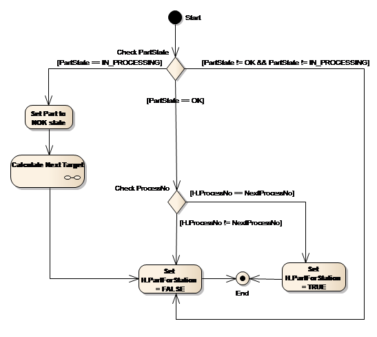
If the work part is IN_PROCESSING state, the Line Control assumes that the processing of the work part has been aborted and the work part is in an undefined state. To ensure that the work part can be processed, the work part will be marked as damaged (NOK state) and moved to the corresponding NOK target of the active processing step and the production release is denied.
If the state is OK, the algorithm moves to the next step, in all other cases the production release will be denied.
-
Compare process numbers
In the second step the process number will be compared with the number of the process which should be executed next. If the process numbers match, the production release will be granted, otherwise the station is not allowed to process the work part.
The following picture will show the complete algorithm for the production release calculation:
Production end
After the station has processed the work part, it must notify Line Control of the processing outcome. This is done using the SetNextStation command, which allows the station to send details such as the processing result, updated work part state, target index, and additional information.
At production end, you can choose whether the target evaluation logic runs on the station or on the server. Regardless of the scenario, SetNextStation can only be called by the process that is currently active for the work part. If the process numbers do not match, Line Control returns an error and does not update the work part dataset.
Station-side logic
If the station evaluates the next target, it selects one of the five possible targets defined for the current processing step. The station cannot specify the next process directly; it must send the target index, which Line Control uses to determine the next processing step.
The station should also provide the new state of the work part, as the server will not interpret the target index or result if a target is specified. If the station omits the state information, the work part state remains unchanged.
Server side logic
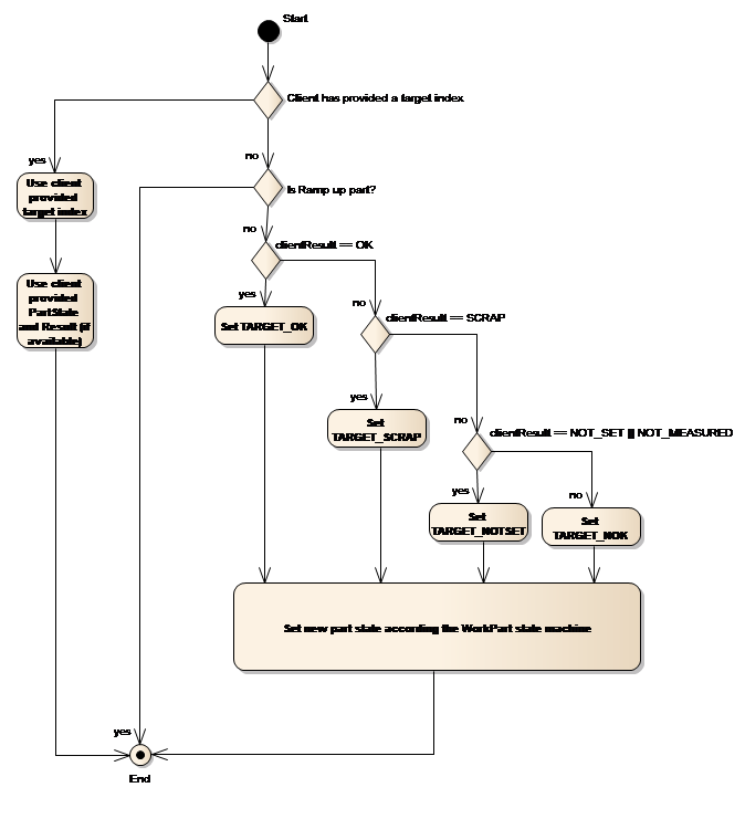
If the server should calculate the next process and the new part state, the client must not send the target index and part state. Line Control uses the last valid part state information and the processing result provided by the process to evaluate the new part state and the next processing step. Both calculations are done independently, so it is still possible that a work part with NOK state could be moved to the OK target.
The calculation of the part state is based on the model described in " 1.2.3 Work part state model ":
State = OK
The processing result will directly mapped as new state, e.g. H.Result = OK → new part state = OK; H.Result = NOK → new part state = NOK.
State = IN_PROCESSING
The processing result will directly mapped as new state, e.g. H.Result = OK → new part state = OK; H.Result = NOK → new part state = NOK.
State = NOK
If the processing result is SCRAPPED, the work part will enter the SCRAPPED state, otherwise, the work part remains in the NOK state.
State = SCRAPPED
The work part will always remain in the SCRAPPED state.
The next processing step will be selected using the processing result only ( H.Result ). The following diagram will show how the next processing step will be evaluated:
Group handling
In Line Control, you can define groups of work parts that move together through production. For example, if you use work piece carriers (WPCs) that hold multiple work parts, those work parts can form a group within Line Control.
A group must have a unique identifier and is managed similarly to a single work part: it is registered at the first process and deleted after the last process is complete.
When registering a group, all member identifiers and their positions must be specified. You cannot add work parts to a group later; the group is treated as a fixed entity. Deleting a group does not delete its members—this is intentional, as the group is a transport mechanism, while processing always occurs on individual parts. When work parts leave the carrier, the group is no longer needed, but the parts remain under Line Control management.
Groups are first-class entities in Line Control, meaning you can store and retrieve additional data for the group itself. This data is only available while the group exists; deleting the group removes its associated data. You can always access individual work parts using their identifiers.
For communication, production requests return all relevant information, allowing the client to select what it needs. For process end notifications, three scenarios are supported when groups are involved:
-
Standard scenario: The station sends results for both the group and its members in a single message. Use this when individual work parts need separate handling but you want to reduce communication overhead. For example, instead of sending 10 separate
SetNextStationmessages for 10 work parts, you send one message with all results, reducing communication time by about 90%. -
Top-down scenario: The station sends only the group result, not individual work part results. This is suitable when the group is processed as a whole (e.g., thermal processes), and all work parts receive the same result. The group result is applied to all members.
-
Bottom-up scenario: The station first sends individual results for each work part. Each message is processed immediately by Line Control. After all parts are processed, the station notifies Line Control that the group has been processed. Line Control then calculates the group’s state and next target based on the states and targets of its members. This scenario is mainly used for backward compatibility, minimizing changes when adapting existing stations to group-based production.
Example
The following picture will show you the typical messages for a work part running through a production:
For the example the group consists of 4 single work parts. In the first step, the group will be created with the process end of "Load Line".
For the example we will assume, that all work parts where processed without any errors, so the work parts and the group are in OK state.
| ID | Result | Before | After | ||
|---|---|---|---|---|---|
Part State |
Next Process |
Part State |
Next Process |
||
GRP001 |
OK |
OK |
281 |
||
WP1 |
OK |
OK |
281 |
||
WP2 |
OK |
OK |
281 |
||
WP3 |
OK |
OK |
281 |
||
WP4 |
OK |
OK |
281 |
||
WP5 |
OK |
OK |
281 |
||
WP6 |
OK |
OK |
281 |
The station hosting process 281 will request the production release and will receive for the group and all work parts a production release. The station will process all work parts and then sends the processing results using the standard scenario:
| ID | Result | Before | After | ||
|---|---|---|---|---|---|
Part State |
Next Process |
Part State |
Next Process |
||
GRP001 |
OK |
OK |
281 |
OK |
610 |
WP1 |
OK |
OK |
281 |
OK |
610 |
WP2 |
OK |
OK |
281 |
OK |
610 |
WP3 |
OK |
OK |
281 |
OK |
610 |
WP4 |
OK |
OK |
281 |
OK |
610 |
WP5 |
OK |
OK |
281 |
OK |
610 |
WP6 |
OK |
OK |
281 |
OK |
610 |
If the station has detected, that the connector was not correctly pressed in at work part WP3, the station will report this with an NOK result for that work part. In this case the group would look like this:
| ID | Result | Before | After | ||
|---|---|---|---|---|---|
Part State |
Next Process |
Part State |
Next Process |
||
GRP001 |
OK |
OK |
281 |
OK |
610 |
WP1 |
OK |
OK |
281 |
OK |
610 |
WP2 |
OK |
OK |
281 |
OK |
610 |
WP3 |
NOK |
OK |
281 |
NOK |
701 |
WP4 |
OK |
OK |
281 |
OK |
610 |
WP5 |
OK |
OK |
281 |
OK |
610 |
WP6 |
OK |
OK |
281 |
OK |
610 |
If even more work parts have defects, the station could decide that the processing of the whole group has failed, even when some of the work parts have been successfully processed:
| ID | Result | Before | After | ||
|---|---|---|---|---|---|
Part State |
Next Process |
Part State |
Next Process |
||
GRP001 |
NOK |
OK |
281 |
NOK |
701 |
WP1 |
OK |
OK |
281 |
OK |
610 |
WP2 |
NOK |
OK |
281 |
NOK |
701 |
WP3 |
NOK |
OK |
281 |
NOK |
701 |
WP4 |
OK |
OK |
281 |
OK |
610 |
WP5 |
NOK |
OK |
281 |
NOK |
701 |
WP6 |
NOK |
OK |
281 |
NOK |
701 |
For the example we will assume, that only WP3 has defect, but the other parts have been processed correctly. If the process 610 requests the production release, this will be granted for the group and all work parts except for WP3 (because WP3 should be processed by the Repair process and is in NOK state).
In this example, process 610 will send its results using the bottom-up scenario. The station will send the first processing result after WP1 has been processed:
| ID | Result | Before | After | ||
|---|---|---|---|---|---|
Part State |
Next Process |
Part State |
Next Process |
||
GRP001 |
OK |
610 |
OK |
610 |
|
WP1 |
OK |
OK |
610 |
OK |
276 |
WP2 |
OK |
610 |
OK |
610 |
|
WP3 |
OK |
610 |
NOK |
701 |
|
WP4 |
OK |
610 |
OK |
610 |
|
WP5 |
OK |
610 |
OK |
610 |
|
WP6 |
OK |
610 |
OK |
610 |
Then work part 2 will be processed and so on. For the example WP6 has also a defect and was reported with NOK result. After all work parts have been processed, the group looks like this:
| ID | Result | Before | After | ||
|---|---|---|---|---|---|
Part State |
Next Process |
Part State |
Next Process |
||
GRP001 |
OK |
610 |
OK |
610 |
|
WP1 |
OK |
OK |
610 |
OK |
276 |
WP2 |
OK |
OK |
610 |
OK |
276 |
WP3 |
OK |
610 |
NOK |
701 |
|
WP4 |
OK |
OK |
610 |
OK |
276 |
WP5 |
OK |
OK |
610 |
OK |
276 |
WP6 |
NOK |
OK |
610 |
NOK |
701 |
The station will now send the SetNextStation message for the group and the Line Control has to calculate the new state and target for the group. For the evaluation of the new state, the Line Control checks if the number of the groups' NOK parts is greater than the configured threshold. If yes, the group will enter the NOK state, otherwise, the group will remain in the OK state.
For the next target, Line Control checks which parts have been processed by process. For this subset the processing step will be taken which at the beginning of the OK chain inside the route list. In this case, this would be the process 276. But if for some reason the process 610 has set a work part to process 900, the processing step for process 900 would be the next target for the group.
| ID | Result | Before | After | ||
|---|---|---|---|---|---|
Part State |
Next Process |
Part State |
Next Process |
||
GRP001 |
OK |
OK |
610 |
OK |
276 |
WP1 |
OK |
OK |
610 |
OK |
276 |
WP2 |
OK |
OK |
610 |
OK |
276 |
WP3 |
OK |
610 |
NOK |
701 |
|
WP4 |
OK |
OK |
610 |
OK |
276 |
WP5 |
OK |
OK |
610 |
OK |
276 |
WP6 |
NOK |
OK |
610 |
NOK |
701 |
Finally the process 276 will send its processing results using the top-down scenario. In this case, all work parts for the process will be evaluated using the global processing result. If the station sends an OK processing result group will look like this:
| ID | Result | Before | After | ||
|---|---|---|---|---|---|
Part State |
Next Process |
Part State |
Next Process |
||
GRP001 |
OK |
OK |
276 |
OK |
… |
WP1 |
OK |
276 |
OK |
… |
|
WP2 |
OK |
276 |
OK |
… |
|
WP3 |
NOK |
701 |
NOK |
701 |
|
WP4 |
OK |
276 |
OK |
… |
|
WP5 |
OK |
276 |
OK |
… |
|
WP6 |
NOK |
701 |
NOK |
701 |
But if the station sends a NOK result, the group would look like this:
| ID | Result | Before | After | ||
|---|---|---|---|---|---|
Part State |
Next Process |
Part State |
Next Process |
||
GRP001 |
NOK |
OK |
276 |
NOK |
701 |
WP1 |
OK |
276 |
NOK |
701 |
|
WP2 |
OK |
276 |
NOK |
701 |
|
WP3 |
NOK |
701 |
NOK |
701 |
|
WP4 |
OK |
276 |
NOK |
701 |
|
WP5 |
OK |
276 |
NOK |
701 |
|
WP6 |
NOK |
701 |
NOK |
701 |