Process Escalation Configuration
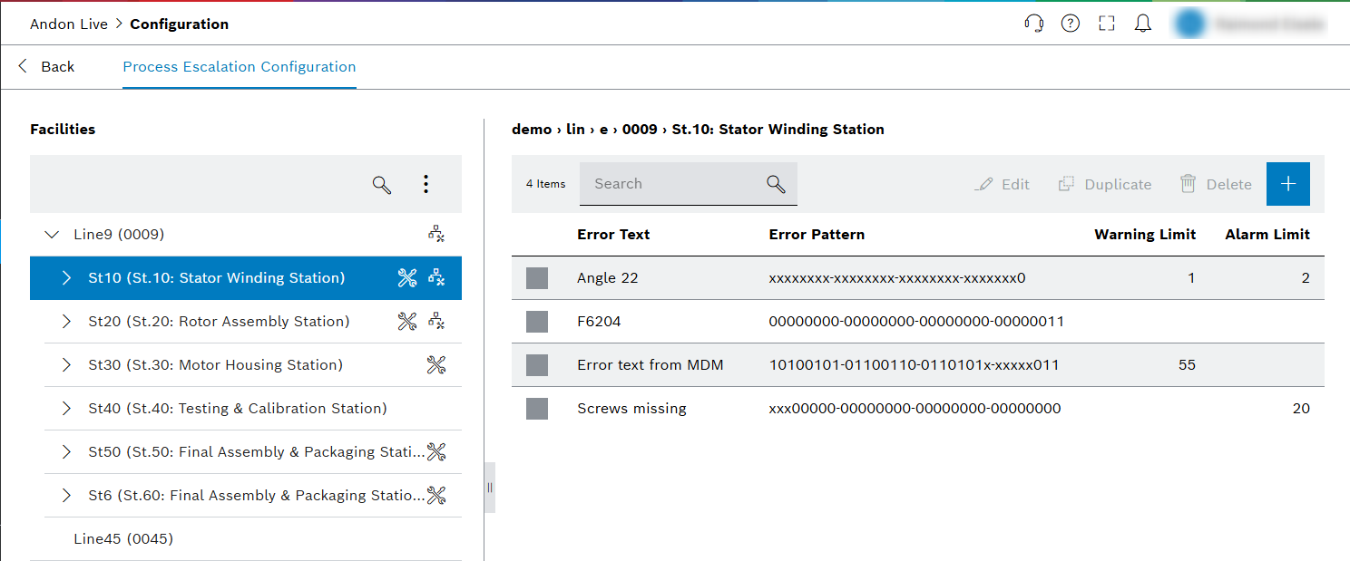
Define error limits and set alarm values for lines and child elements for the Process Escalation view.
| Element | Description |
|---|---|
|
|
|


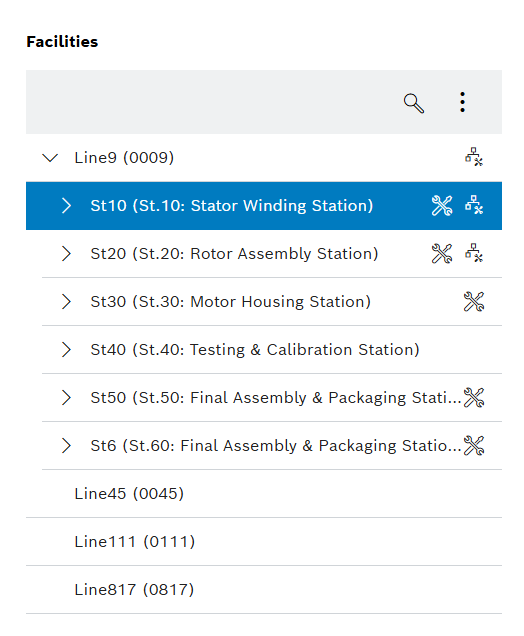
Detailed view of the navigation tree
The individual lines are displayed in the navigation tree. Clicking a line entry opens the child elements of the respective line, provided that the line has been configured: Configure a line for the first time.
Lines are divided into the following child elements:
-
Stations (St)
-
Station indices (Si)
-
Functional units (Fu)
-
Working positions (Wp)
-
Tool positions (Tp)
| Element | Description |
|---|---|
No marking |
Line without configuration (e.g. Line: 6) |
|
Line has been configured, the child elements are displayed in the navigation tree (e.g. Line: 5) |
|
Line or station during which an error pattern configuration was created (e.g. Line: 5). |
|
Facility with error pattern configuration (e.g. Si: 1) |


|
A combination of |
Error Pattern
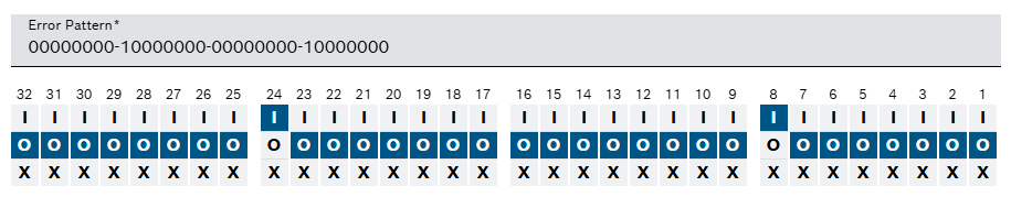
The error pattern consists of 32 error bits. These can either be entered as plain text in the Error Pattern field or set by clicking on the buttons.
There are three different settings for each bit:
-
0 : A 0 must be present at this position.
-
1 : A 1 must be present at this position.
-
X : This position of the error pattern is no longer taken into account.
|
The error is displayed only if the 0 s and 1 s of the error match the error pattern. X is ignored. If multiple pattern would match (due to X) then the most specific one (the one with the lowest number of X) is used. If there are multiple patterns with the same specificity, the first match is used (first match based on a technical point of view, not from user perspective). |
|
Process Escalation Tool is able to handle complex error patterns. |
The following examples are purely based on the capabilities of Process Escalation Tool. Limitations of related systems are not taken into account.
(Examples are done with a 4-bit error code to keep it simple. The same applies to 32-bit error codes.)
Example 1: Classic error patterns
Historically, each error bit represents exactly one error, so a maximum number of 32 errors can be transmitted with the error pattern.
Bit 1: Not enough air pressure
Bit 2: Not enough oil pressure
The machine could either send 0011 to represent this state with one telegram or two telegrams with the respective values 0001 and 0010.
The error pattern configuration within Process Escalation Tool for two telegrams has to be 0001 and 0010 to count the errors individually. If one telegram is used then the pattern 00x1 and 001x has to be used to count the errors individually.
In contrast to a binary code where 0011 would be a new error (e.g. no parts available), this is typically just the combination of two errors into one telegram.
Example 2: Binary based error patterns
If the machine sending the telegram and all previous systems are able to handle binary codes, then
Process Escalation Tool is able to handle the case which was explicitly excluded in the first example.
Bit 1: Not enough air pressure
Bit 2: Not enough oil pressure
Bit 1+2: No parts available
In this case one telegram has to be sent for each error, but combinations would be possible which drastically increases the number of possible errors (2^32 -1).
The pattern configuration in this case has to be 0001, 0010 and 0011 to count the errors individually.
Individual error patterns
Individual error patterns can be defined for each station and its child elements. If errors from lower levels are not intercepted and displayed with their own error pattern, these errors are displayed at a higher level.
Prerequisite : The relevant defined error pattern applies to this error.
Example:
At station level, the error pattern "0000000‑00000100‑00000000‑00000100" has been created. If this process error occurs at the child elements but is not defined there, the error is intercepted and displayed at station level.